

What Are the Top 10 Types of Mold Parts?
Mold parts may look like small steel details, yet each one influences how a mold fills, cools, opens, and produces a consistent component. A polished cavity face forms the product’s surface. A worn guide pin can introduce misalignment. Even a tiny vent matters when trapped air leaves burn marks or incomplete filling. The parts work as a system.
In this introduction, fictional mold-design expert Daniel Mercer offers a guiding line: “A mold is only as reliable as the parts that locate, shape, and release the plastic.” This is an editorial quotation, not a verified statement from a real industry professional. That distinction matters. Technical decisions deserve clear sources, not borrowed authority.
What Are the Top 10 Types of Mold Parts? This guide examines the components commonly found in injection molds, including cavities, cores, inserts, runners, gates, ejector pins, guide pillars, bushings, cooling channels, and vents. Their exact designs vary with the resin, part geometry, production volume, and machine setup. Some molds combine functions. Others need extra components to handle deep ribs, complex slides, or demanding tolerances. The list is a starting point, not a universal specification. A detail that seems minor on a drawing can affect maintenance, cycle time, and finished-part quality. Practical review helps. So does a little skepticism.
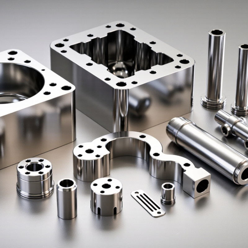
Core and Cavity Components That Form the Molded Part
The cavity shapes the outside of a molded part, while the core forms its inner surfaces. Together, they control dimensions, texture, and many visible details. Small errors matter. A shallow mismatch at the parting line can leave a noticeable step or flash.
The main forming components include cavity plates and core plates, which support the tooling; cavity and core inserts, which create specific surfaces; and slides and lifters, which form side openings or undercuts. Shutoffs seal moving sections against one another. Parting-line inserts create local edges, while vents let trapped air escape. Replaceable wear inserts protect areas exposed to repeated contact. These components work as a system, not as isolated pieces.
Good design depends on the part’s geometry, resin behavior, and expected production volume. Draft angles help the part release, and cooling channels near the cavity and core can reduce uneven shrinkage. I have seen a detail look clean in a CAD model but prove difficult to polish or inspect in steel. That trade-off deserves an early review. A practical check compares the molded sample with the drawing, especially around corners, thin ribs, and moving shutoffs.
What Are the Top 10 Types of Mold Parts? - Core and Cavity Components That Form the Molded Part
| No. | Mold Part | Main Function | Typical Location | Practical Design Considerations |
|---|---|---|---|---|
| 1 | Cavity Insert | Forms the external surfaces of the molded part, including its visible faces and outer details. | Usually installed in the stationary half of the mold. | Surface finish, shrinkage allowance, cooling, and replaceability should suit the part and production volume. |
| 2 | Core Insert | Forms internal surfaces, openings, recesses, and other details on the inside of the part. | Often located in the moving half; may be designed as a separate replaceable insert. | Draft, strength, cooling, and resistance to wear matter, especially for slender core features. |
| 3 | Mold Base and Plates | Supports and aligns the mold assembly, while holding inserts, guiding components, and ejection hardware. | Forms the structural frame of the stationary and moving mold halves. | Plate stiffness, adequate support, machine mounting, and access for cooling and maintenance are important. |
| 4 | Sprue Bushing | Directs molten plastic from the machine nozzle into the mold’s runner system or cavity. | Mounted in the stationary half, aligned with the injection machine nozzle. | Nozzle-seat fit, flow path, sealing, and removal of the solidified sprue should be considered. |
| 5 | Locating Ring | Positions the mold accurately relative to the injection machine’s platen and nozzle. | Attached to the stationary side of the mold. | Its dimensions must match the machine interface and keep the sprue bushing aligned with the nozzle. |
| 6 | Leader Pins and Bushings | Guide the two mold halves into alignment as the mold closes. | Installed between the stationary and moving halves, typically around the mold perimeter. | Correct clearance, alignment, lubrication, and protection from contamination help reduce wear and damage. |
| 7 | Ejector Pins | Push the cooled part off the core after the mold opens. | Move through the ejector plate and bear on selected areas of the part. | Pin locations and contact areas should limit visible marks, part distortion, and sticking. |
| 8 | Runner System | Carries molten plastic from the sprue to one or more gates in a cold-runner mold. | Formed in channels between mold plates, leading to the cavity or cavities. | Channel size and layout affect filling, pressure loss, material use, and runner removal. |
| 9 | Cooling Channels | Circulate a cooling fluid to remove heat from the mold and help control cycle time and part quality. | Drilled or formed within mold plates and near the cavity and core surfaces. | Channel position and flow should promote even cooling without weakening the mold or causing leaks. |
| 10 | Vents | Allow trapped air and gases to escape as molten plastic fills the cavity. | Often placed near the end of the fill path, parting line, or other air-trap locations. | Vent depth must suit the resin and process: vents should release gas while limiting plastic flash. |
Note: Mold layouts vary by part geometry and process. Some molds use hot runners, slides, lifters, or other specialized components in place of, or in addition to, the parts listed above.